|
For the current Blender version (2.8) download this Handle Panel add-on file.
For quick creating parents of your handle objects, you can use this additional utility (for Blender 2.8). It adds an Empty object as the parent of the active object. It also resets the local croordinate system of the active object (the handle), allowing for a more intuitive "Limit Location" settings.
For Blender 2.7 and 2.6, download this Handle Panel add-on file, described in the 4th section of this tutorial.
For Blender 2.4, download this HandlePanel.py script file, described in the 3rd section of this tutorial.
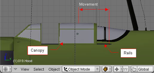
Canopy hood on the La-5 slides backwards, along the rails, while it is being opened (see Fig. 1.1).
|
|
Of course, the cockpit canopy can be moved manually along its rails, in this model. Yet following such a trajectory always requires a special precision. Is there something in Blender, which automatically would restrict the movement of this element to its rails?
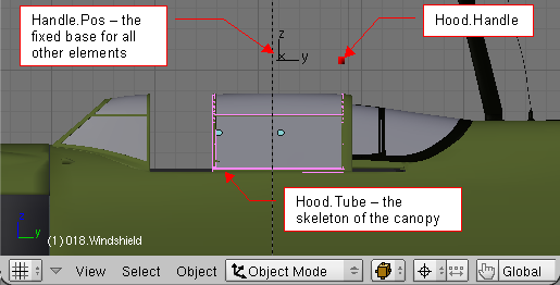
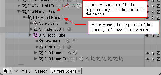
Yes it is. There are constraint object modifiers. I decided not to apply them to the canopy hood directly. Sometimes it can be difficult to select such an object among the others. In the real machine, the cockpit canopy assembly was built from four parts: the skeleton, made from a steel tube, the outer frame, formed from a dural tin, the layer of organic glass between them, and a small release handle. All these parts have been reproduced in this model. The steel tube inner frame is the parent of the rest. It is very easy to select unintentionally the glass object, instead of this frame. When you move it, the rest of the canopy assembly will remain on its place. Thus, it is better idea to create an artificial "handle" that would be located in a more accessible place. It will be the parent of the inner frame. The solution is shown in Fig. 1.2 and in Fig. 1.3:
|
I have added a canopy handle – 019.Hood.Handle. This object is the parent of the whole canopy assembly – it follows its movements. Hood.Handle object is located relatively far away from the the model, for easier selection.
|
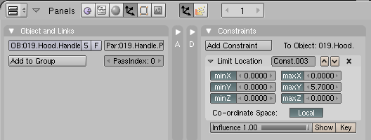
My idea is to use the Hood.Handle object to move the canopy. It is located on a separate layer, which should be excluded from the rendering. To restrict its movement to one-dimensional slide along the rails, I have added an empty object – 019.Handle.Pos - to this model. It is the "base" of the Hood.Handle movement, and its parent. Handle.Pos object is fixed to the body of the airplane. Hood.Handle object has a constraint, which restricts its movement to the segment matching the rails. It is shown on the Fig. 1.4.
|
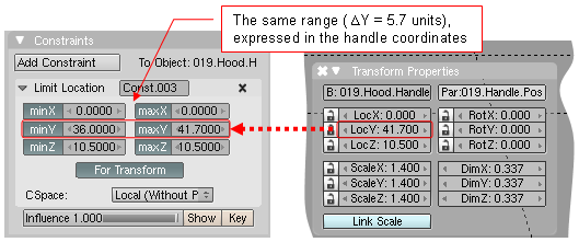
Examine the settings of the constraint shown in the Fig. 1.4. It is a Limit Location constraint. (The Fig. 1.4 shows how it looked like in Blender 2.45. Its ranges are expressed relative to its parent. I think that it is easier to explain the idea using this old version of this constraint. The more "novel" one is shown in Fig. 1.5). The only allowed movement of the Hood.Handle object is along the Y axis (note that only the minY and maxY values create a non-zero range). Because the Local option of this constraint is turned on, range distances are measured from the parent of the Hood.Handle – the Handle.Pos object. It is the only reason of the Handle.Pos existence – to mark the handle neutral position. It is sometimes impossible to use any model part for this purpose – they have their centers in other places, ant not always they can be displaced. That's why it is easier just to use an Empty object here.
In later Blender versions, the convention of specifying the limit ranges has changed. Currently you have to write there the same coordinates, which are visible in Transform Properties window (Fig. 1.5):
|
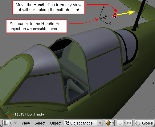
So – here is the first effect. You can easily grab the handle, from any view, not worrying about the distance nor direction of your movement. The handle "knows" its path, and will never exceed its limits:
|
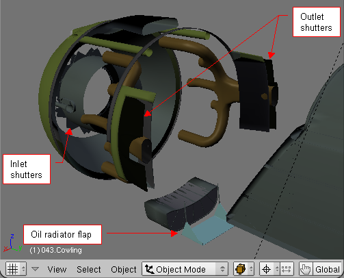
Canopy handle is a simple case. You will learn the real power of movement handles, analyzing the solution devised for the engine cooling system. It is demonstrated on Fig. 2.1:
|
Although in the real airplane every of the elements, shown on the Fig. 2.1, had its own control, their position was always similar: opened at the low speed (or on the ground), and nearly closed at the high speed. It would be the best, if it all these parts could move, following a single control handle. But how to obtain such effect? The outlet shutters rotate around a skewed axes. The oil radiator flap has two actuators, which should follow its movement. And there are two rings of inlet shutters, each of them rotating along its own axis – one ring clockwise, the second – counterclockwise. How to join all these different movements with one handle?
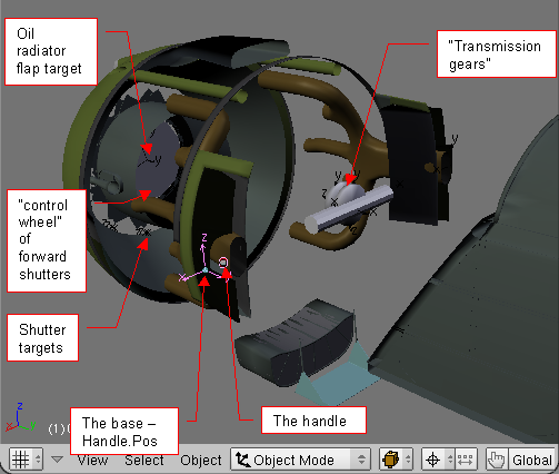
Well, the solution is presented below, on the Fig. 2.2:
|
The movement of the handle is restricted by Limit Location constraint, relative to its parent – another empty Handle.Pos object. The displacement of the handle moves other helper (empty) objects. They are tracked, using Lock Track constraints, by the “transmission gears”, located between the outlet shutters. The cylinder mirrors the movement of right shutter to the left shutter (using a Stretch To constraint). The double wheels use Locked Track constraint to transfer the handle movement into a rotation – one clockwise, the another – counterclockwise. Their rotation is repeated by the wheels inside the rings of inlet shutters. For every inlet shutter there is an empty “target” object, “fixed” to the control wheel. Each shutter rotates along its axis, tracking its “target” through Locked Track constraint.
This "virtual machine" uses the constrains that were available in Blender 2.43 (in the time when I created this model). In the newer Blender releases Aligorth (the Blender developer responsible for the constraints) has added their new types. One of them is Transformation, which you can use as the “universal transmission gear”. You can obtain the effect, described above, with simpler constraint system that uses a few Transform constraints. (Example of such you can find in my later P-40B model).
What’s more, in Blender 2.43 the Limit Location worked always along the global coordinate system axes, even with in the Local mode! When I tried to rotate my model, this constraint would create mess with the engine cowling elements… This gave me the first impulse to write a Python script that would overcome this problem. In effect, I created an universal “control panel” to pose the models. I named it Handle Panel. Although the Limit Location is already fixed, I still use this script. It is easier to control the model using the GUI controls, than to search for the handle objects, dispersed in many different places.
I use this script for convenient control of the moveable parts. It is named HandlePanel.py, and available from here. Download it, and save into your Blender scripts directory - it will appear in Blender Scripts Window, as Scripts=>Misc=>Handle Panel menu command. It is also included as one of the Text Editor datablocks of the La-5 model, used in this tutorial. You can open it there and run by pressing [Alt]-[P].
(For Blender 2.5 there is the Handle Panel add-on - see the next section.)
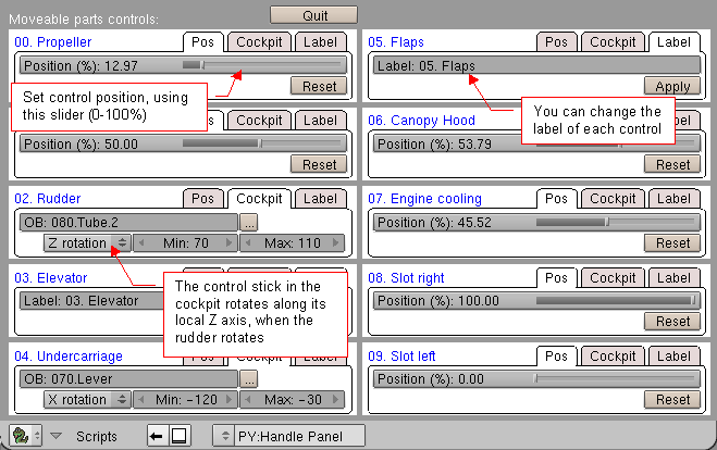
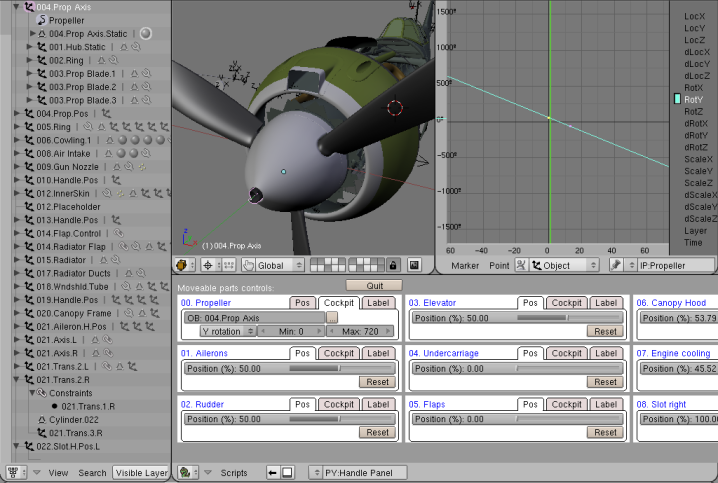
For the La-5 model, Handle Panel screen in Blender 2.4 looks like on Fig. 3.1:
|
For every handle that exists in the model, this script displays a single panel containing 3 tabs: Pos, Cockpit, Label. You can see ten of such panels in Fig. 3.1.
I use this add-on for convenient control of the moveable parts. It is named scene_handle_panel.py, and available from here. Download it, and add to your Blender. (Here you can find the description how to do it). Once installed, you will find this add-on in the Scene category of the Blender User Preferences:Add-ons window.
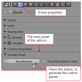
When you activate this add-on, it adds the Handle Panel to your Scene properties tab: Fig. 4.1:
|
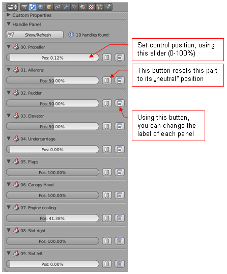
When you press the Show/Refresh button on this panel, it will search your file and display the control panel for each found handle (Fig. 4.2):
|
Each control panel contains 3 controls: Pos, Reset, Label. You can see ten of such panels in Fig. 4.2.
On startup, Handle Panel script searches the current scene for the handle objects, that should be presented as the panels. This means, that you can utilize it for your own models. It will show a panel for every object, that:
The 019.Canopy.Handle, presented in details on Fig. 1.2 – 1.6, is an example of such an object. Create similar ones in your model. It is up to you, what will be "connected" to the movement of this object. Test the newly created handle, moving it along the predefined track, with the Limit Location constraint active. Handle Panel script will use the information from this constraint, to determine the path for this object.
“Handle” objects are also usable for animations: connect them to a set of IPO curves. Use Handle Panel to prepare handle position for every keyframe. Notice, that many La-5 handles (the rudder, the elevator, propeller, ailerons and slats) have IPO curves assigned. Their keyframes were created using the Handle Panel script.
|
Fig. 6.1 shows the IPO curve, that controls the rotation of the propeller. Keyframes for this curve were prepared using the Handle Panel script. This motion is responsible for the motion blur of the propeller blades. This effect occurs, when you turn the MBLUR Renderer toggle on.