|
Typical airplane contains many different openings in its fuselage and wings. Blender has some Boolean commands. You can use them, to create a hole in a mesh, but they can sometimes produce unwanted results. Usually there are problems with the faces around the new edge of intersection. I have found myself many times on deleting the ones, originally created by the Boolean operation. After their removal, I had to create manually a more "regular" face pattern around such a hole.
Ultimately, I concluded, that I need a tool, which would create the common edge of two arbitrary meshes. It was more practical to create the new faces around it manually, not spending time on removing the automatically created ones. So, here is such tool. I have found it useful, maybe you also utilize it.
Since Blender 2.72 there is a similar, standard Intersection (Boolean) command. (Actually in Blender 2.8 you can find it in Edit Mode, in the Faces menu). It resembles this add-on and produces similar results. The difference is that it splits the original faces along the newly created intersection edge, or removes one of the dissected mesh parts.
However, the standard Intersect command and the plugin presented below provide the user different result options. I suggest to use both of them. (This plugin add its commands to a different menu, so there is no conflict). In my daily work I use the standard command when I want to split the mesh faces, and the plugin command when I want to rearrange the mesh topology around the intersection edge.
Here you can download the object_intersection.py add-on file for Blender 2.8.
Here you can download the object_intersection.py add-on file for previous Blender versions (2.5..2.7).
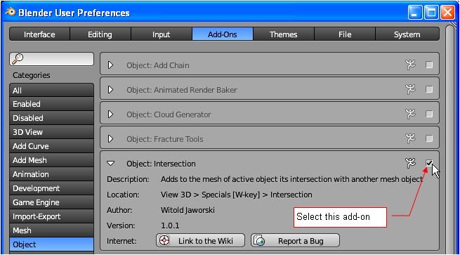
To follow this tutorial, you should install this Intersection add-on into your Blender environment. (Here is the the description, which explains how to do this).
|
|
|
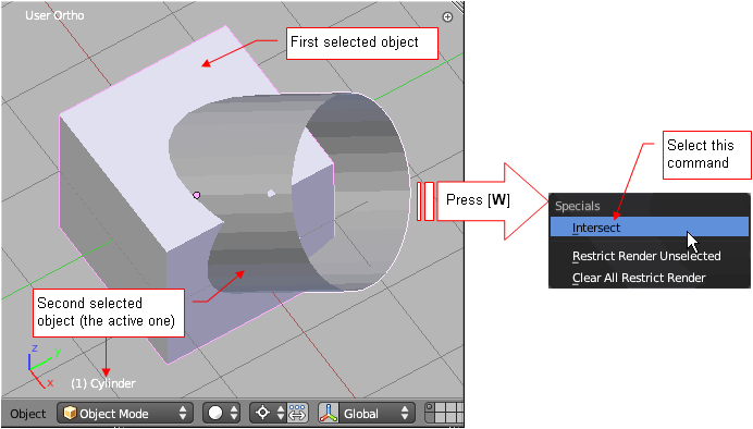
Select the Intersect command (you can find it at the top of this menu). It opens a dialog box with the options of this operation (Fig. 3):
|
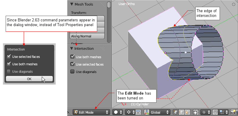
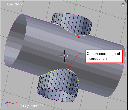
When you click the [OK] button, this script switches Blender into the Edit Mode. It adds the intersection edge loop(s) to the mesh of the active object. This new edge is not connected to any of the mesh faces, and its vertices are selected. Thus, if you are not happy with the result, just press the [X] key to remove it and try again.
|
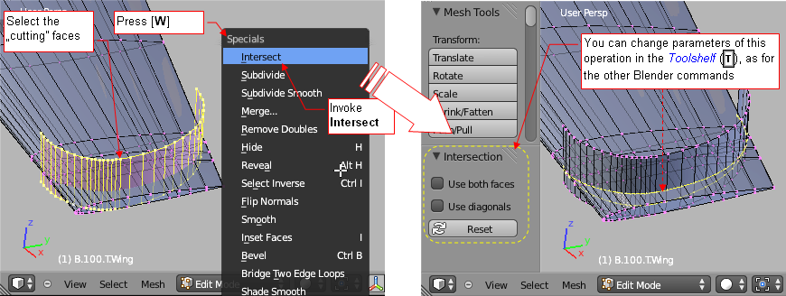
In Edit Mode , select the faces you want to cut with the others, and then: in Blender 2.8 open the Edges menu (in Blender 2.7 press the [W] key to open the Specials menu). Select the Intersect Faces (in Blender 2.7: Intersect) command from there, so it will add the new edge loop (or loops) to the mesh. You can alter this result using the command options from the Tool options panel.
|
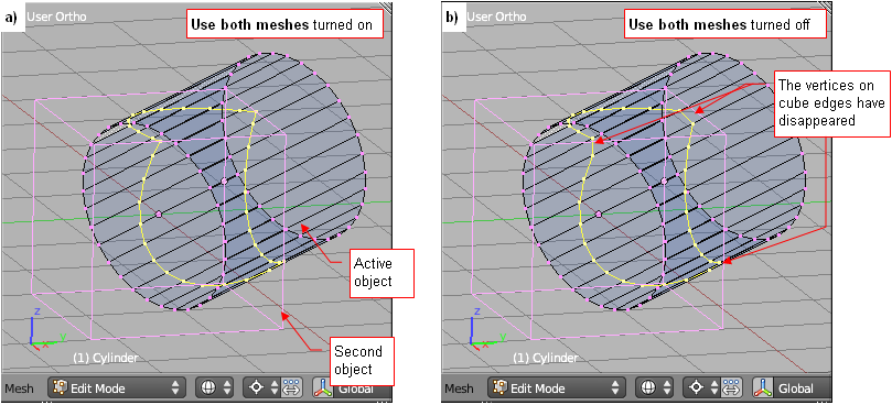
If you want to get the edge consisting only points lying on the edges of the active object - turn off the default option Use both meshes. You will get the result that is generally less accurate (Fig. 5b). However, it will be easier to integrate it into the existing grid, because there will be less triangular faces.
|
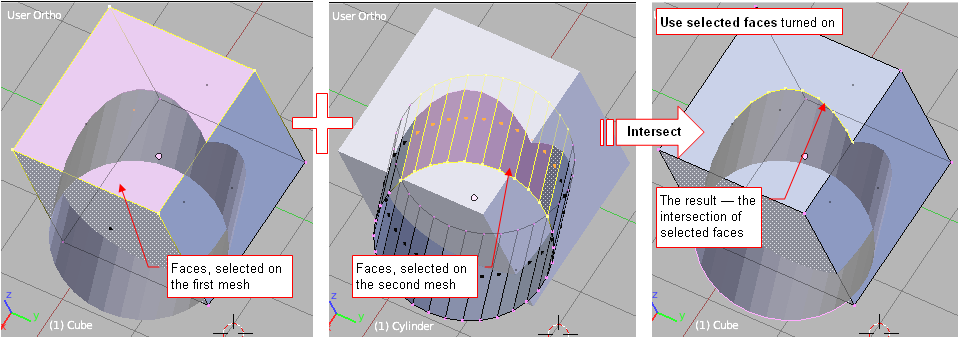
Use selected faces is enabled by default. If you do not want to limit the scope of the processed meshes - disable it.
In Edit Mode this option is not available. If you want to exclude some faces from this operation - hide them before, using the Hide Selected command ([H]). After completing thei command, you can unhide them ([Alt]-[H] – Show Hidden)
|
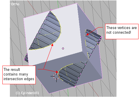
The hardest part of the algorithm, used in this plugin, is the fragment responsible for connecting the intersection points into one or more continuous edges. Usually it works fine, but sometimes the errors occur. The chance for such errors is higher, when the result contains several separate edges (Fig. 7):
|
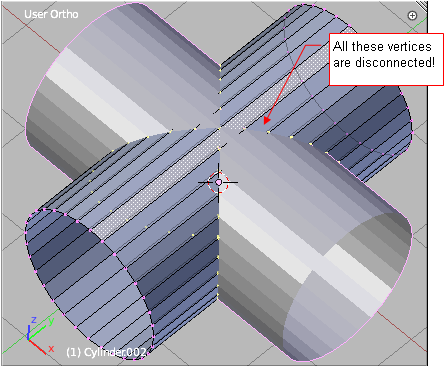
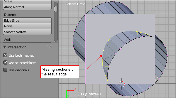
Of course, if there are just a few such errors, you can just quickly correct it, connecting the vertices by hand. Be aware the situations, where the edges of one mesh exactly intersect the edges of the second mesh. That can happen, for example, when you try to find the intersection of two identical cylinders (Fig. 8):
|
In this particular case, as in Fig. 8, all intersection points have been found, but the script failed to join them into one edge. Of course, if you will use two different cylinders, you will get the correct result (Fig. 9):
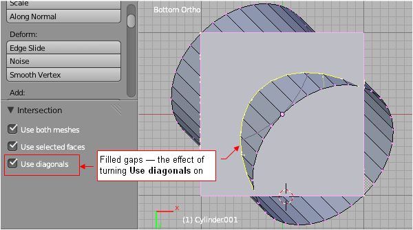
In case of problems - remember, usually just a small rotation or displacement of one of the meshes allows the script to connect the edge points properly. As a precaution, I have added to the parameters of the script the Use diagonals option.
|
Sometimes you can improve the result, just turning the Use diagonals option on (Fig. 11):
|
|
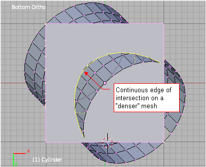
On the other hand - the obtained edge is less "handy" for further work, because now it has twice as many vertices than before. In fact, I left this option "just in case." In this and similar cases can also improve the result by adding additional edges to the meshes (Fig. 12):