<?xml version='1.0' encoding='utf-8' ?>
<?xml-stylesheet type="text/xsl" href="header_e.xsl" ?>
<body PageTitle="Finding cross sections between two arbitrary meshes" PageHeader="Tutorials">
<br/>
<div>
<p>
Typical airplane has many different holes, in its fuselage and wings. Blender has some Boolean 
commands. You can use them, to create a hole in a mesh, but they can sometimes produce not 
exactly the results, you want. Usually there are problems with the faces around the new (crossing) edge. 
I have found myself many times on deleting the ones, originally created by the Boolean 
operation. After their removal, I had to create manually a more “regular” face pattern 
around such hole. 
</p>
<p>
Ultimately, I concluded, that I need a tool, which would produce just the common edge of two 
crossing meshes. It was more practical to create the new faces around it manually, not spending time 
on removing the automatically created ones. So, here is such tool. I have found it useful, 
maybe you also utilize it.
</p>
</div>
<div>
<p><a href="downloads/scripts/CrossSection.py">Here</a> you can download the <b>CrossSection.py</b> script file.</p>
<p>
To follow this tutorial, you should place the Cross Section script into your Blender script 
directory (here is the <a href="scripts-010_e.xml">tutorial</a>, 
which explains how to do that).
</p>
</div>
<div class="subheader">1. Crossing two meshes in six clicks</div>
<div>
<p>
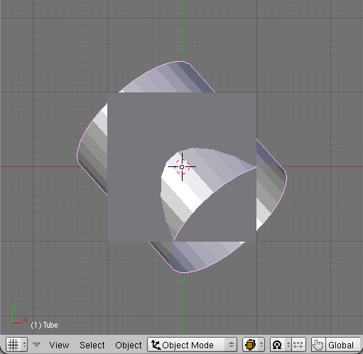
To the default Blender cube I have added a second mesh object – a cylinder:</p>
<table cellSpacing="0" cellPadding="0pt" align="center">
	<tr align="center" valign="top">
		<td>
			<A href="images/scripts/030/image11.png" target="_blank" title="click to see larger image">
				<IMG height="299px" src="images/scripts/030/image11s.png" align="center"/>
			</A>
		</td>
		<td>
			<A href="images/scripts/030/image12.png" target="_blank" title="click to see larger image">
				<IMG height="299px" src="images/scripts/030/image12s.png" align="center"/>
			</A>
		</td>
	</tr>
	<tr align="center" valign="top">
		<td><spanl>Fig. 1.1. Meshes, that will be crossed.</spanl></td>
		<td><spanl>Fig. 1.2. The same meshes, but from isometric view.</spanl></td>
	</tr>
</table>
</div>
<divf>
<p>
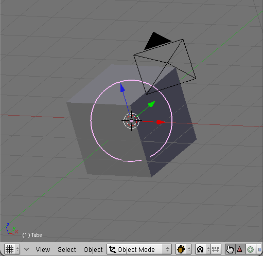
If you want to repeat exactly what I have done: I have just added new cylinder it in the "three-quarters" 
isometric view (Fig. 1.2.). It was created 
using <b>Add=>Mesh=>Cylinder</b> command, with following parameters: <b>vertices</b>: 32, 
<b>radius</b>: 1, <b>depth</b>: 2, <b>no cap ends</b>.
</p>
<p>Now:<br/> 
<li>Select the Tube object (the cylinder on the Fig. 1.1);</li>
<li>Add to the selection the Cube object;</li>
<li>Issue <b>Object=>Scripts=>Cross Section</b> command. A dialog box will appear:</li>
</p>
</divf>
<div>
<table cellSpacing="0" cellPadding="0pt" align="center">
	<tr align="center" valign="top">
		<td>
			<A href="images/scripts/030/image13.png" target="_blank" title="click to see larger image">
				<IMG height="400px" src="images/scripts/030/image13s.png" align="center"/>
			</A>
		</td>
	</tr>
	<tr align="center" valign="top">
		<td><spanl>Fig. 1.3. Cross Section dialog box.</spanl></td>
	</tr>
</table>
</div>
<divf><p>Do not change anything on the dialog box. Just click the <b>OK</b> button.</p></divf>
<div>
<table cellSpacing="0" cellPadding="0pt" align="center">
	<tr align="center" valign="top">
		<td>
			<A href="images/scripts/030/image14.png" target="_blank" title="click to see larger image">
				<IMG height="400px" src="images/scripts/030/image14s.png" align="center"/>
			</A>
		</td>
	</tr>
	<tr align="center" valign="top">
		<td><spanl>Fig. 1.4. The result – cross section edge, added to the active object.</spanl></td>
	</tr>
</table>
</div>
<divf>
<p>
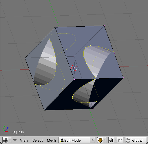
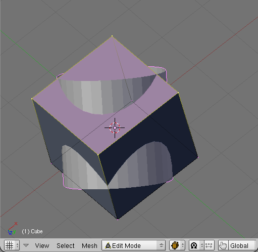
Almost immediately (because both meshes are rather simple) the active object has been 
switched into Edit mode. The new edge – containing the vertices of the cross section – 
has been added to it. Do with the cross-section edge what you want. If you are not satisfied 
with this result – just press <b>[X]</b> to remove it, and then <b>[Tab]</b> to switch back 
into Object mode.
</p>
</divf>
<div class="subheader">2. Script options – details of its dialog box</div>
<div>
<table cellSpacing="0" cellPadding="0pt" align="center">
	<tr align="center" valign="top">
		<td>
			<A href="images/scripts/030/image21.png" target="_blank" title="click to see larger image">
				<IMG src="images/scripts/030/image21.png" align="center"/>
			</A>
		</td>
	</tr>
	<tr align="center" valign="top">
		<td><spanl>Fig. 2.1. The script dialog box.</spanl></td>
	</tr>
</table>
</div>
<divf>
<p>
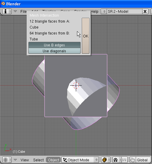
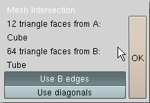
The dialog box of the Cross Section script contains a short description of operation, 
and two option toggles.
</p>
<p>
<b>Description of the operation</b> informs about the number of the faces, that will be examined, 
in each mesh. The “A” mesh is the mesh of the active object – the object, which you have 
selected as the second one. The cross section edge is always added to the “A” mesh. 
From the operation description you can also learn the name of the “A” mesh (in Fig. 2.1 – Cube).
The second mesh is called “B”. This dialog box presents analogical information for it, like for
the “A” mesh: number of triangle faces,  mesh name (in Fig. 2.1. – Tube).
</p>
<p>
<b>Use B edges</b> option. If you switch it off, the result will contain the vertices found 
along the “A” mesh edges, only. It is turned on by default, what means that the result will contain 
vertices obtained from both meshes;
</p>
<p>
<b>Use diagonals</b> option. During the calculations every four-vertex face is turned into two triangles, along the 
shorter diagonal. If you want to have include the results of crossing such diagonals with opposite 
mesh faces, turn this option on. Usually you will need it in special cases, only (like calculation 
of the cross section of two cubes).
</p>
</divf>

<div class="subheader">3. Crossing mesh fragments</div>
<div>
<p>
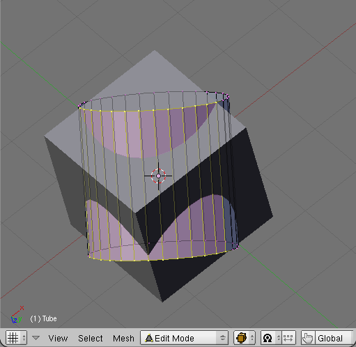
It is possible to calculate the common edge for selected fragments of the object's meshes, only. 
To do it, in Edit mode just select the faces, you want  to use for these calculations, in each mesh. 
Then select both objects for the Cross Section operation, like in the previous section:
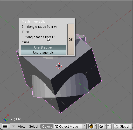
</p>
<table cellSpacing="0" cellPadding="0pt" align="center">
	<tr align="center" valign="top">
		<td>
			<A href="images/scripts/030/image31.png" target="_blank" title="click to see larger image">
				<IMG height="299px" src="images/scripts/030/image31s.png" align="center"/>
			</A>
		</td>
		<td>
			<A href="images/scripts/030/image32.png" target="_blank" title="click to see larger image">
				<IMG height="299px" src="images/scripts/030/image32s.png" align="center"/>
			</A>
		</td>
	</tr>
	<tr align="center" valign="top">
		<td><spanl>Fig. 3.1. Selected fragment of the first mesh.</spanl></td>
		<td><spanl>Fig. 3.2. Selected fragment of the second mesh.</spanl></td>
	</tr>
</table>
</div>
<divf>
<p>Issue the <b>Object=>Scripts=>Cross Section</b> command. A dialog box will appear. 
Compare it to the one from Fig. 3.3. Have you noticed, that the one from Fig. 3.3 declares 
smaller number of the faces?</p>
</divf>
<div>
<table cellSpacing="0" cellPadding="0pt" align="center">
	<tr align="center" valign="top">
		<td>
			<A href="images/scripts/030/image33.png" target="_blank" title="click to see larger image">
				<IMG height="400px" src="images/scripts/030/image33s.png" align="center"/>
			</A>
		</td>
	</tr>
	<tr align="center" valign="top">
		<td><spanl>Fig. 3.3. Cross Section dialog box - notice smaller number of faces in the operation description.</spanl></td>
	</tr>
</table>
</div>
<divf><p>When you click the <b>OK</b> button, you will see the result:</p></divf>
<div>
<table cellSpacing="0" cellPadding="0pt" align="center">
	<tr align="center" valign="top">
		<td>
			<A href="images/scripts/030/image34.png" target="_blank" title="click to see larger image">
				<IMG height="400px" src="images/scripts/030/image34s.png" align="center"/>
			</A>
		</td>
	</tr>
	<tr align="center" valign="top">
		<td><spanl>Fig. 3.4. The result of crossing two mesh fragments – a corresponding fragment of crossing edge;</spanl></td>
	</tr>
</table>
</div>
<divf/>
<div class="subheader">4. Troubleshooting</div>
<div>
<p>
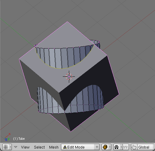
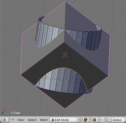
I have worked hard on the algorithm that connects properly the cross-section vertices, 
which have been found. Anyway, sometimes it may happen, that you will miss some important 
fragment of this edge. It is usually a problem of the script with determining the order 
of the vertices along the cross edge. Such case you can see in Fig. 4.1.
</p>
</div>
<div>
<table cellSpacing="0" cellPadding="0pt" align="center">
	<tr align="center" valign="top">
		<td>
			<A href="images/scripts/030/image41.png" target="_blank" title="click to see larger image">
				<IMG height="400px" src="images/scripts/030/image41s.png" align="center"/>
			</A>
		</td>
	</tr>
	<tr align="center" valign="top">
		<td><spanl>Fig. 4.1. Improper result of cross section calculation – missing a part of the crossing edge;</spanl></td>
	</tr>
</table>
</div>
<div>
<p>There are two possible workarounds:
<li>move a little one of the objects – usually the problem appears, when an edge from one mesh 
crosses exactly an edge from another mesh. Even minimal movement will resolve the problem;</li>
<li>reduce the number of the faces for the cross operation, selecting the “active fragments” 
of the mesh – as shown in the paragraph 3. You can still build whole edge from a few pieces, obtained by subsequent calls
to the Cross Section script;</li>
</p>
</div>
</body>
